



The configurable BMS up to 48 V.

3 to 16 cells, up to 250 A continuous. Cell chemistry, protection parameters and interfaces are configured, not redeveloped.

Anori Low-Voltage BMS held up against a blue sky and trees, backlit

In drones, robots, boats, off-grid storage and power tools, the BMS decides on safety, remaining runtime and approval. If it does not match the cell chemistry and the applicable standard, even the best cell in the battery pack will not help.

The product

A BMS that fits your battery pack.

The Anori Low-Voltage BMS is a configurable battery management system for battery packs with 3 to 16 cells in series, up to 48 V system voltage and 250 A continuous current.

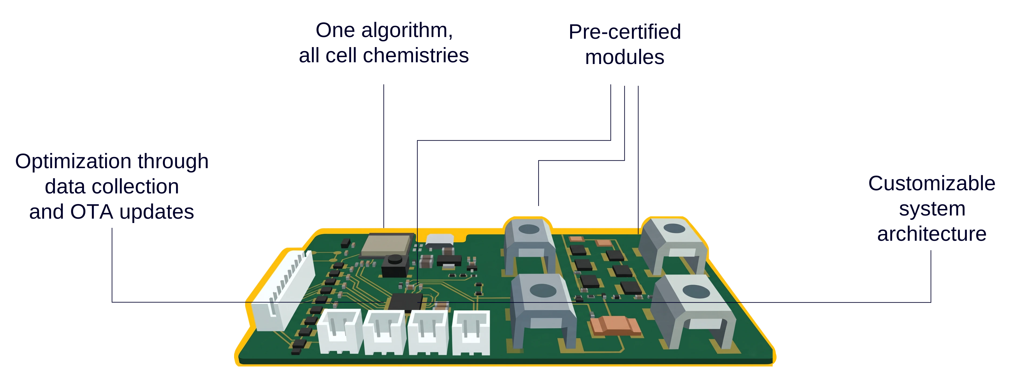
Anori Low-Voltage BMS with labelled key features: one algorithm for all cell chemistries, pre-certified modules, customizable system architecture, and optimization through data collection and OTA updates
The key features of the Anori Low-Voltage BMS at a glance

It monitors every single cell, controls charging and discharging and protects the battery pack against overload, deep discharge and overheating. What sets it apart from other systems is the architecture: safety logic, state estimation, balancing, communication and diagnostics are independent, already validated function blocks. For your project we assemble the right combination from them instead of forcing an existing system to fit your application. That is how you get a BMS tailored exactly to your battery pack, including the test evidence your certification rests on. In days rather than months, small series included.

You define what your battery pack needs: cell chemistry, voltage range, protection thresholds, balancing behaviour, interfaces and the standards that apply to your application. From that we assemble your BMS out of validated blocks, each with its own test suite and validation evidence. Because our block library grows with every project, adaptation gets faster and cheaper with every customer instead of starting from scratch each time. If your requirement changes after the first test, you get the adapted version back in the shortest possible time, not after the next development cycle.

01

One algorithm for every cell chemistry

At its core runs our proprietary Anori algorithm: a multi-stage state estimation that evaluates every cell individually instead of relying on fixed voltage curves. A chemistry-specific parameter set tunes the algorithm to your cell. LFP, NMC, LTO, NCA and sodium-ion all run on the same firmware. SoC deviation stays below 2 %.

02

Tailored, not a compromise

You state your requirements and receive a BMS that matches them: protection limits, communication protocols, feature set and standards precisely for your application. No off-the-shelf system you have to live with, and no in-house development over months.

03

Connected and updatable

Telemetry optionally over CAN, RS485, Bluetooth, WiFi or LTE, plus configurable event logging and automated over-the-air updates. If you use the connection, you see across the entire service life how your battery packs are actually stressed in the field, as a basis for warranty handling, remote diagnostics and lifetime reporting.

Fundamentals

What is a battery management system?

A battery management system (BMS) is the electronics that monitor, protect and control a lithium-ion battery pack.

It measures the voltage, current and temperature of every cell, estimates state of charge and state of health, balances differences in charge between cells, and disconnects the battery pack before overcharging, deep discharge, short circuit or overheating can damage it. Without a BMS, a lithium battery pack is neither safe nor compliant to place on the market.

For battery pack manufacturers, the BMS is therefore the component that determines safety, certifiability and usable capacity. It is also the component that is hardest to source: standard systems cannot be adapted to new cell chemistries or interfaces, and an in-house development typically takes six to twelve months. This is exactly the gap the Anori Low-Voltage BMS closes, by moving adaptation out of development and into configuration.

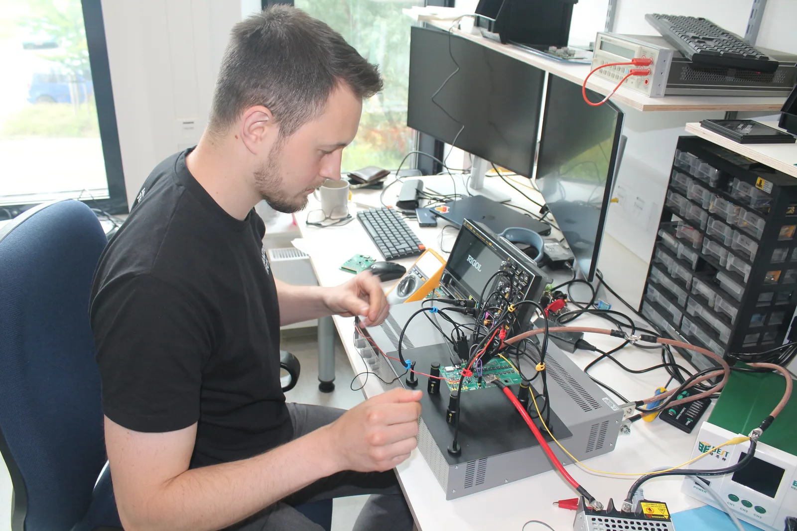
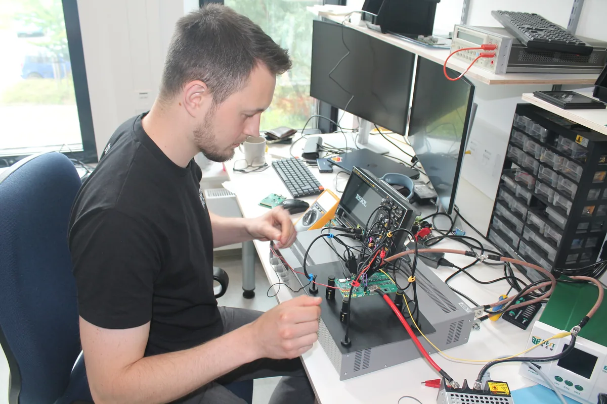
Stefan testing the Low-Voltage BMS at the measurement bench in the Anori lab, connected to the cell stack
Voltage curve of an LFP cell across state of charge 4.0 V 3.5 V 3.0 V 2.5 V 2.0 V 100 % 75 % 50 % 25 % 0 % State of charge (SoC) Cell voltage (V) Almost flat: 20–80 % SoC

Why is state-of-charge estimation so difficult with LFP?

Because LFP cells have an almost flat voltage curve across much of their charge range. Between roughly 20 and 80 percent state of charge, cell voltage changes by only a few millivolts. A purely voltage-based estimation method, which still works for NMC, can no longer reliably tell whether a battery pack is half full or nearly full. In practice this produces remaining-runtime figures that are off by double-digit percentages.

The Anori BMS solves this with a multi-stage per-cell state estimation: instead of a fixed voltage curve, the algorithm combines measurements from every individual cell across several stages and stays chemistry-agnostic as a result. In typical application scenarios, state-of-charge estimation deviates by less than 2 percent. A new cell chemistry therefore only needs a new parameter set, not new firmware.

Datasheet

Technical specifications of the Anori platform

The figures below show what the Anori platform offers at its current stage. For your battery pack you select exactly the functions and interfaces your application needs. The values and features listed are therefore optional configuration choices and not automatically part of every BMS configuration.

Key figures of the Anori Low-Voltage BMS
Cells in series3 to 16
System voltageup to 48 V nominal
Continuous current250 A
Pulse current500 A for 1 s
Cell chemistriesLFP, NMC, LTO, NCA, sodium-ion
Balancingactive up to 2.5 A, passive up to 50 mA
SoC accuracy< 2 %
Dimensions150 × 90 × 18 mm
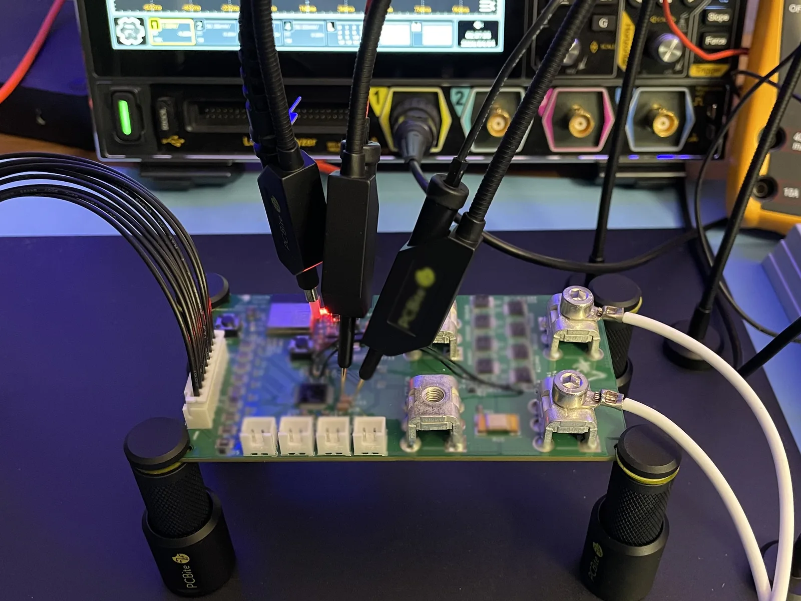
Technical view of the Anori Low-Voltage BMS board with its components and conductor traces
Show all technical data

Values and functions are optional and are matched to the requirements of your battery pack.

Cells and battery pack

Cell voltage sensing3 to 16 channels
Parallel operationsupported
Series operationup to 4 modules

Measurement and state estimation

Current measurement accuracy< 100 mA
Methodmulti-level per-cell state estimation, chemistry-agnostic

Protection functions

Cell voltageconfigurable over- and undervoltage protection (OVP / UVP)
Pack voltageconfigurable over- and undervoltage protection (OVP / UVP)
Currentconfigurable overcurrent and short-circuit protection (OCP / SCP)
Temperatureconfigurable over- and undertemperature protection (OTP / UTP)
HeatingPWM control up to 20 A for pack heating in cold operation

Interfaces and connectivity

CANCAN 2.0B
Victron integrationVE.Can
LINLIN bus
RS485RS485
BluetoothBluetooth Low Energy (LE 5.0)
WLAN2.4 GHz, IEEE 802.11 b/g/n
CellularLTE NB-IoT / LTE-M
LocationGNSS

Data and software

TelemetrySoC, cell voltages, current, temperature, status messages
Event loggingconfigurable
Updatesautomated over-the-air updates

Mechanics and environment

Temperature range−30 °C to +60 °C
Electronics protectionconformal coating to IPC-CC-830
Service life10 years
Electrical transientsISO 7637-2/-3, ISO 16750-2 (load dump, reverse polarity, jump start), LV 148
ESD / burst / surgeEN 61000-4-2 / -4-4 / -4-5

Regulatory framework

CE conformityEMC, radio equipment (RED), Battery Regulation, Cyber Resilience Act
Vehicle EMCUN ECE R10
Functional safetyunder development to IEC 61508 (SIL 2) and ISO 26262 (ASIL C)
Standards & certification

Regulatory requirements considered from day one

What gets certified in the end is your complete system, not the BMS on its own. Our job is to make sure it passes that assessment. From the first design decision onwards, the Anori Low-Voltage BMS is aligned with the regulations that apply in your application, and we test against their requirements before your battery pack goes to a test laboratory.

Certification is where battery projects lose the most time, usually because it only becomes clear late which regulations actually apply. That is why it comes first with us: safety analyses and support during your testing are itemised in the quote, so you know the effort from the outset and do not have to recalculate in the middle of the project. Because the platform modules are already pre-assessed against common standards, you assess the complete system in your project and not every individual function from scratch. The team behind it comes from series development in automotive and industrial electronics and is qualified accordingly for this standards work.

Application Regulations that typically apply here
Drones & UAV EU 2019/945 & 2019/947, EN 4709-001; defence: IEC 61508, MIL-STD-461/-810
Robotics & AGV Machinery Regulation (EU) 2023/1230, ISO 13849 / IEC 62061, IEC 62619
Marine ISO 23625, Recreational Craft Directive 2013/53/EU
LEV & special vehicles UN ECE R136, UN ECE R10, EN 50604-1, ISO 26262
Off-grid & storage IEC 62619, IEC 63056
Power tools & appliances EN 62841 (battery protection functions)

Status: July 2026. This mapping is the starting point, not the answer. For your specific battery pack it depends on where it is installed and who places it on the market. That is exactly what we clarify at the start of a project, not at the end.

How it works

Four steps. Your finished BMS.

You define the requirements. We deliver a configured, certifiable BMS and collect the battery data over its lifetime so you can keep improving your battery pack.

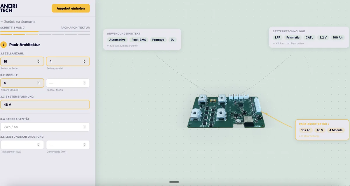
Step 1: enter cell chemistry, voltage and interfaces in the Anori configurator
1

Configure online

Enter cell chemistry, voltage level, interfaces and required functions in the Anori configurator.

Step 2: Anori adapts the standardised BMS platform to the configuration
2

We adapt the platform

Your configuration is applied to the standardized hardware. Adjustments happen in software, not in a redesign.

Step 3: BMS prototype under test in the Anori lab, preparing for certification
3

Prototype & certify

Pre-qualified modules and certification support get your battery pack through validation with minimal effort.

Step 4: the finished Anori BMS is delivered and improved further in the field
4

Deliver & keep improving

Hardware ships. Software, analytics and updates accompany your battery for 10+ years.

Configure your BMS

Applications

Six worlds, one platform.

Every application places its own demands on protection functions, interfaces and standards. What changes is the configuration, not the hardware.

Drone in flight, an application for the Anori Low-Voltage BMS in drones and UAVsAI-generated image
Application 01

Drones & UAV

The challenge

Every gram counts, and the remaining runtime has to be right before the aircraft takes off. A misjudged remaining capacity is not a comfort issue here, it is a safety risk.

What Anori delivers

Multi-level per-cell state estimation keeps SoC deviation below 2 % even at high discharge rates, and current measurement works to better than 100 mA. Protection parameters and limits are set in software for the specific flight profile.


Autonomous transport robot in a warehouse, an application for the Anori Low-Voltage BMS in roboticsAI-generated image
Application 02

Robotics

The challenge

High load peaks, tight installation space, short development cycles. Otherwise every hardware revision on the robot triggers a BMS revision, and with it a new test cycle.

What Anori delivers

250 A continuous and 500 A pulse cover drive and startup peaks on the same board, and 150 × 90 × 18 mm fits tight installation spaces. When the robot changes, the configuration changes, not the board.

Sailing yacht in a harbour, an application for the Anori Low-Voltage BMS in marine useAI-generated image
Application 03

Marine

The challenge

On board there is no workshop within reach. Salt, vibration and continuous operation come together, and lithium on board is governed by its own standards.

What Anori delivers

The design takes ISO 23625 for lithium-ion battery systems on small craft into account. 250 A continuous covers propulsion and house bank, VE.Can integrates the BMS directly into existing Victron installations, and the conformal coating to IPC-CC-830 is designed for damp environments.

E-scooter, an application for the Anori Low-Voltage BMS in light electric vehiclesAI-generated image
Application 04

LEV & special vehicles

The challenge

Short model cycles, hard price pressure, and UN ECE R10 as a requirement. In these volumes an in-house development per model never pays off.

What Anori delivers

Pre-compliance work on UN ECE R10 is already running at platform level, and functional safety is designed along ISO 26262. CAN 2.0B and LIN integrate the BMS into common vehicle architectures. Each model is configured instead of developed.

Mobile energy storage unit outdoors, an application for the Anori Low-Voltage BMS in off-grid storageAI-generated image
Application 05

Off-grid & storage

The challenge

No technician on site, continuous operation over years, and LFP makes it harder: the flat voltage curve renders voltage-based state-of-charge estimation imprecise.

What Anori delivers

Multi-level per-cell state estimation keeps SoC deviation below 2 % even on the flat LFP curve. That makes autonomy calculable instead of estimated. LTE NB-IoT and automated OTA keep the storage system reachable and up to date even without a local network.

Battery-powered tool, an application for the Anori Low-Voltage BMSAI-generated image
Application 06

Power tools

The challenge

Power tool batteries deliver short, very high current spikes on startup and stall, on top of shocks, dust and vibration on the job site. Space inside the tool battery is tight, leaving little room for extra electronics.

What Anori delivers

500 A pulse current for one second covers startup and stall, with configurable overcurrent and short-circuit protection acting before that point. For cold job sites the BMS drives a pack heater via PWM. The compact configuration fits common battery form factors without adding weight.

Frequently asked

Technical questions about the low-voltage BMS.

LFP, NMC, LTO, NCA and sodium-ion. The state estimation algorithm works chemistry-agnostically: it uses multi-level per-cell state estimation rather than a voltage curve fixed to one chemistry. A new cell chemistry therefore needs a new parameter set, not new firmware.

3 to 16 cells in series, meaning battery packs with 12 V, 24 V and 48 V system voltage. Continuous current is 250 A, and pulses up to 500 A are covered for one second. Modules can be connected in parallel, and up to four modules in series. The platform architecture is designed to scale across voltage levels; the product focus today is entirely on the low-voltage range.

CAN 2.0B, VE.Can for Victron integration, LIN, RS485, Bluetooth Low Energy (LE 5.0), WiFi, plus LTE NB-IoT and LTE-M for connectivity without a local network. GNSS is available for location and time reference. Which interfaces are populated and enabled is defined in the configuration.

Current measurement works to better than 100 mA, and state-of-charge estimation stays below 2 % deviation. This is achieved through multi-level per-cell state estimation, which remains reliable even on the flat voltage curve of LFP.

Actively and passively, depending on how the battery pack is designed. Active balancing shifts charge between cells at up to 2.5 A and makes sense wherever usable capacity and efficiency matter. Passive balancing equalises through resistors at up to 50 mA and is sufficient for applications with low cell drift.

Yes. The BMS is configured for marine applications and designed against the requirements of ISO 23625 for lithium-ion battery systems on small craft. VE.Can allows it to be integrated directly into Victron installations. Which other regulations apply to marine applications is listed under standards & certification. We pass on the current conformity status transparently on request.

Yes. Interfaces, protocols and protection parameters are defined during configuration so that the BMS fits your system architecture. CAN 2.0B is standard; VE.Can, LIN, RS485, BLE, WiFi and LTE are added depending on the configuration.

After configuration you receive the quote within 24 hours and the prototype in 10 days. Adjustments after the first test run through the software configuration and require no new hardware cycle.

Last updated:

Does this fit your battery pack?

Send us cell chemistry, voltage and current. The quote arrives within 24 hours, the prototype in 10 days.

Prefer to talk? +49 151 6701 1710 or team@anoritech.com

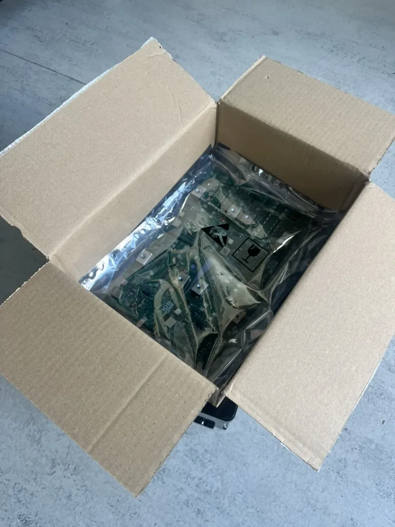
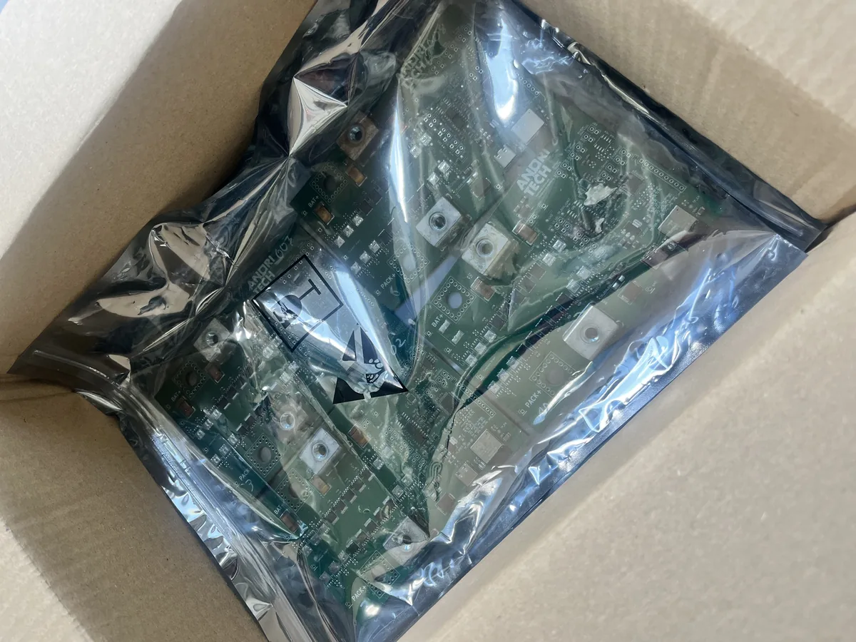
Anori Low-Voltage BMS packed and ready to ship, in an open box